
Advanced Shading and Camera Models in Computer Graphics
Advanced Shading
Recommended book : https://www.realtimerendering.com/
We can do shadow, reflection, refraction, all by ray tracing.
But It’s possible to do a hybrid of rasterization and ray tracing!
Fixed-function Blinn-Phong model
Phong Shading
- A fixed-function model is too restricted
- What are “specular” and “diffuse” for your material?
- “Too much flexibility” - can produce unrealistic results
Physically-based Shading
- Programmable shaders can support a physics-based BRDF model
- Just like physics-based animation, physics-based BRDF will make your image look “realistic” under different lighting etc.
Microfacet models
Instead of considering an ad-hoc “glossiness”, consider the distribution of micro-mirrors (microfacets)
- Smooth surfaces have more “aligned” micro-mirrors
- Glossiness = Parameter that describes the distribution
Dielectrics and conductors
- Dielectric (i.e., non-metals) - reflect the color of light
- Conductors (i.e., metals) - colored reflections
Fresnel reflections
- Physics-based definition of reflectance at a boundary
Albedo (reflectance) textures
Albedo means fraction of light that is reflected by a body or surface.
- Material “colors” should encode only its “reflectance”, that is, you should remove any influence due to illumination
Deferred shading
- Render only the input to shading as a first pass, then run shading as a second pass by drawing a screen-sized quad
- Save time for shading pixels that end up not being visible
- Only trace shadow ray that’s con
More Physics-based shading
- Translucent materials (human skin, wax, etc.)
- Energy conservation - reflection shall not increase light
- Layered materials (clear yellow-painted steel vs gold)
- Better rough surfaces
They are common across rasterization and ray tracing
(what you learned in ray tracing can be used in rasterization)
Non-photorealistic rendering (NPR)
- Not everything needs to be “photorelistic”
- Some stylization such as “cartoon”-like shading
Cel Shading (Toon shading)
Art form, no correct answer of what to do
Basic idea (Geometric normals)
Bent normals
- Using geometric normals produce “unnatural” results for cel shading
- Manually (!) edit normals for shading to make it look right
Outlines and Feature lines
Cell-look needs some distinct feature lines (outlines)
- Draw back-faces by making an object slightly larger, then draw front-faces with Z-test enabled
- Use image processing to add outlines after rendering (using normals and depth buffers as cues)

More Non-photorealistic rendering
- Paint-like rendering (brush strokes, hatching, etc.)
- Additional deformation to make an object look correct on images (e.g., a character in a Japanese anime)
- Consistent feature lines/outlines
Camera effects
Cameras in the real world can add interesting “imperfection” to images
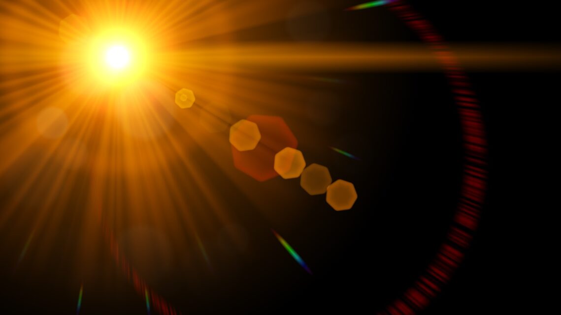
Lens flare
- Caused by interreflections between lenses
Naive approximation Implementation
- draw transparent patterns according to the location of the light source and the camera
Bokeh (Depth of Field)
- caused by out of focus so some part of image is blurred
Naive approximation Implementation
- Input: a (sharp) rendered image and its depth buffer
- Define the size of blur according to the distance to focus
Motion blur
- To indicate something is moving fast
- Essentially the same as DoF; blur along motion this time
- Caused by accumulation of light over time
- Camera has a finite shutter speed
- Faster shutter speed = less light
- Typically around 10 to 20 msec
- Object can move while the shutter is open => result in Blurring of photos
Volumetric effects
Fog
- Change the color according to the distance to the camera
Clouds
- Optically similar to fog, but localized
- Two popular approaches are billboards and ray marching
Billboards
- Textured quads with transparency
- Drawing a lot of them will give you “volumetric” feeling
Tree can also be considered as a volumetric object (lots of leaves and branches in small space)
^Fixed-function fog and billboards are usually inexpensive, but less flexible and may not achieve realistic results
Ray marching
- “March” into a volume along the viewing direction per pixel, compute illumination at each point, and accumulate
- Essentially the same algorithm as ray marching for implicit surfaces, but with different computation and output
- Fragment shader is suitable for this (lots of examples available)
^Modern games use ray marching if the cost is acceptable
Hair and fur
- Similar to billboards, but oriented in a special manner
- Hair: ribbon-like strands
- Fur: “fins” and “shells” from the base surface
Shadows and Reflections
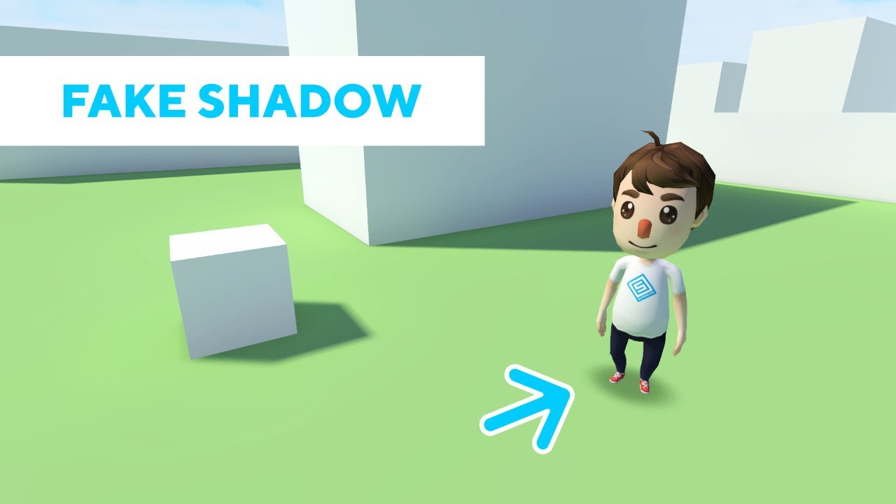
Fake shadow - Shadow blob
- Fake shadow (incorrect shape, no “self-shadowing”)
- Draw a textured quad with some transparency
Shadow mapping
- What is not visible from a light source = in shadow!
- Two pass: 1. from a light source, 2. from a camera
Reflection
Planer reflection
- Render the same scene twice by reflective transformation
- Render into a cube map and use it as an env. map
- Works well if reflected objects are far away
Refraction
- Refracting vectors with env. map does not work quite well
Screen-space illumination
- Use rasterized normals, depth, and colors as approximation of the scene geometry
- Essentially performs approximate ray tracing
- Can be used for various illumination effects
Further complexities
Level of Detail
Hierarchical culling
Shader simplification
- Far objects don’t need detailed shading
Progressive mesh
Transition to ray tracing
- More people started using ray tracing for interactive applications including video games
- Modern GPUs have hardware-accelerated ray tracing
https://developer.nvidia.com/blog/nvidia-turing-architecture-in-depth/
Why ray tracing…
- Significantly simplified pipeline
- Simplified algorithms to achieve advanced effects
- Shadows, reflections, refractions, etc.
- They are all done “right” (e.g., depth of field)
- Automatic culling (what’s outside the view is not touched)
- Automatic deferred shading (only visible pixels are shaded)
Why not ray tracing?
- Computationally (and financially) too costly
- Ray tracing is not as fast as rasterization for now (in some cases, they are getting comparable)
- Ray tracing-capable GPUs are expensive to buy (and maybe not so many users can run your program)
- Switching to rasterization-based design to ray tracing-based design takes a lot of effort
Advanced camera model
For Pinhole Cameras:
- Small pinhole => gathers little light
- Large pinhole => blurry images
Solving Large pinhole issue: Use Lens
By tuning the focal length at the lens, we can control Bokeh effect.
Note that Pinhole camera has no bokeh effect.
Thin Lens Model
- Idealized theoretical model of lense
- All rays focus at focal distance
- Rays bend at the center plane
- How thin? just a plane
Simulating a Thin Lens
Two parameters for simulating the thin lens:
- Size of the lens ®
- Distance from the film to the focal plane (d)
- focal plane is the plane on the focused objects
- focal length (f) is not the distance from the film to the focal plane (d)
Given a pixel location
- Sample a random point on the lens
- Ray-focal plane intersection through the centre
Then trace an actual ray through the two points:
- Sampled point on the lens
- Intersection point on the focal plane
Do the same thing many times and take the average on the pixel
Sampling a Lens in detail (e.g. by Rejection sampling)
- Sample a square until the point is in the circle
2
3
4
5
point.x = (2.0 * random - 1.0) * radius
point.y = (2.0 * random - 1.0) * radius
} until (in_circle(point))
return point
Lens Formula
where
- is the focal length
- is the distance from the film to the lens
- is the distance from lens to the object
- Note that
- Lens has mm (property of lens)
- How far you want to focus?
Aperture
Control the size of a hole which light goes through
- unit of Aperture : f-number = focal length / aperture
- small f-number means bright lens
Small aperture ~= pinhole = all focused
Simulating Aperture…
- Sample a square until the point is in the aperture
1 | repeat { |
Typical Parameters of Camera model for realistic simulation
- Focal length = 40 mm
- Aperture = 10 mm
- f-number = focal length / aperture : 3.5
- Film size: 36 mm x 24 mm
Colours
Color in Computer Graphics only store RGB
Why RGB?
- Our retina can only see
- Light intensity cones:
- Small wavelength : Blue
- Medium wavelength : Green
- Large wavelength : Red
We are dealing with signals.
Spectrum and RGB
Spectrum to RGB
- Compute responses to spectrum as XYZ
- Convert XYZ to RGB
RGB to Spectrum
- Spectrum has much more info than RGB
- “An RGB to Spectrum Conversion for Reflectances”
- “Reproducing Spectral Reflectances from Tristimulus Colors”
- Data-driven approach
High Dynamic Range
- RGB values can go beyond 1.0
- in real world, the intensity of light is very bright!
Human eye can only capture:
- 2^14:1 brightness difference
- 14 bits
Monitor can only capture:
- 255:1 brightness difference
- 8 bits
We need Tone Mapping to convert an HDR value into 0-1 or (0-255)
Linear Scaling
- Scale and clamp
Non-linear Scaling
- Use a function to “compress” HDR into 0-1
Gamma Correction
Once you have converted HDR:
- 0.5 is not necessary displayed as “0.5”
- Nonlinear mapping on a monitor
- Need correction to input tone-mapped value


